Rotor stator motor works 4 – internal flow around rotors and stators Types of ac motors [construction, parts working principle] more
Schematic diagram of the interaction between the stator and rotor
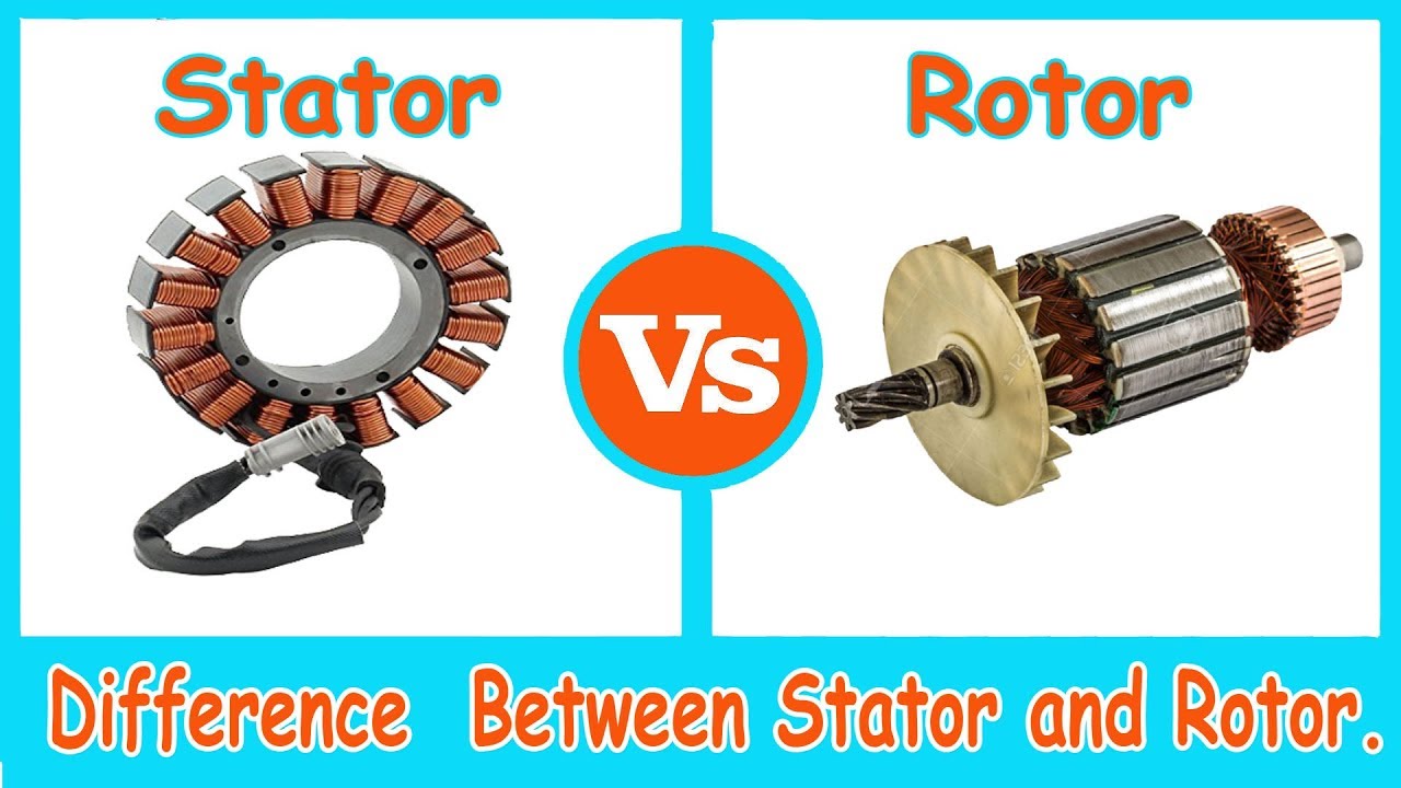
Difference between stator & rotor (with comparison chart)
Outer stator and inner rotor arrangement of the proposed scheme ( other
Stator rotor innerStator and rotor lamination Difference between stator & rotorContactor as an important part of the motor control gear.
Types of single phase induction motorsStator rotor Stator rotor indicatesStator and rotor of im..

2: rotor-stator configuration. the flow goes from left to right and the
Construction of 3-phase induction motorStator rotor alternator difference between construction definition electrical Rotor statorStator rotor.
Stator motors theengineerspostSingle phase motor What is a rotor and stator and how a motor worksSchematic of rotor-stator interaction..

Schematic of rotor/stator model.
Rotor stator windings angleRotor-stator arrangement. Rotor statorRotor stator vidos.
What is step motor stack length?Stator rotor motor induction phase construction ac inside cage motors variable frequency drives hub two main enclosure Intermediate rotor disc generatorStator rotor ac configuration generator correct question.
Schematic of the experimental facility showing the rotor and stator
Motor rotor stator induction phase single figure diagram wiring motors types ac working electrical gif controlRotor stator Schematic presentation of rotor and stator configuration applied inRotor motor length stack stator step bearings single diagram next.
Stator ipm rotor shaft geometry magnetsSchematic of rotor-stator interaction. Stator rotor laminationStator rotor arrangement.

Motor control starter diagram wiring rotor contactor stator part resistance auto using important gear ac3 starters contactors transformer ratings selected
Stator and rotorRotor stator between difference cage squirrel core definition made The 3d geometry of the interior permanent magnet ipm motor: (a) statorRotor stator applied configuration.
Flow rotor stator cavity rotors internal stators around inflow rate superimposed radial schematic figure small largeSchematic diagram of the interaction between the stator and rotor Stator rotor differenceStator phase rotor induction listrik.


